Examples of Proper Fire Pump Equipment Installations
March 23, 2015Whether it is through a new fire pump sale or from a service or repair troubleshooting call, we see a lot of fire pump mechanical rooms. Occasionally we see an installation of new fire pump equipment which catches our eye in a good way — that is, the installing contractor did an exemplary job with installing the equipment. The proper installation of fire pumps and controls is covered in NFPA 20, as well as in NEC Article 695. Going forward, when we see exceptional work in this regard, we will point out the aspects that make the work stand out. We want good work recognized!
For this blog, we feature an installation in Phoenixville, PA, installed by H & H Systems, Inc.
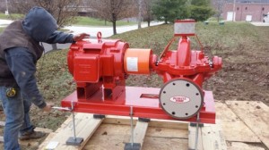
The installation is of a Peerless horizontal split-case fire pump, along with controller, jockey pump, and accessories. As with many new installations, there is not a lot of space in this particular mechanical room. Nonetheless, this room made very efficient use of the space given, and the equipment was installed in a way that will allow for future servicing with minimal trouble. Typically future servicing of equipment is not often a high priority when the layout of a pump room is planned. For the installation noted, it will be a pleasure to service the equipment down the road.
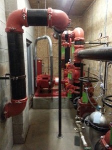
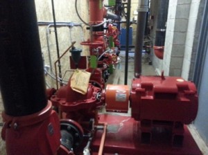
In the above photos, notice the clear path of entry and exit. This is a very small room — most of today’s mechanical rooms are — but should the fire pump or fire pump motor ever need to be replaced or repaired, there is room to safely move about the room.
The plumbing fittings, as well as the electrical materials, were of high quality and were neatly placed. All piping was straight, clean, and properly secured. The jockey pump piping and sensing lines were installed in a clean, clear way, and were not crammed into a corner of the room. Isolating the jockey pump and performing repairs down the road will be a very simple and straightforward task.
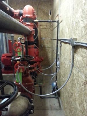
The controller wire penetrations were made through the bottom and side of the controllers instead of through the top of the controller. This is important in order to prevent metal shavings from contaminating the electronics within the controller. Far too many of the installations we see neglect this point, but not this one.
The fire pad was clean and properly set, and the pump base was properly grouted and secured. This will help eliminate any misalignment problems long term, and also helps to make the room look organized.
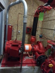
The casing relief valve was properly located on the pump discharge flange, and piped to a floor drain. A separate drain was used to collect the packing draining and that’s directed to a drain as well. The material used for this drain was an inexpensive yet non-corrosive material which will resist clogging, and was completed in a non-cluttered manner. The air release valve (see the blue valve on the right of the next picture) was properly located on the top of the fire pump casing. Even though spray from the air release valve is typically minimal, note that the contractor took extra care to pipe and direct any potential water to a floor drain. Nice touch!
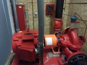
The room was well lit, properly heated (a detail that is often underrated in the winter months in Pennsylvania), and had a suitable floor drain.
Topping off this work was the fact that H & H Systems was prepared for the pump commissioning and start-up, and was not scrambling to install pump sensing lines or to wire up the motors. Well done!